





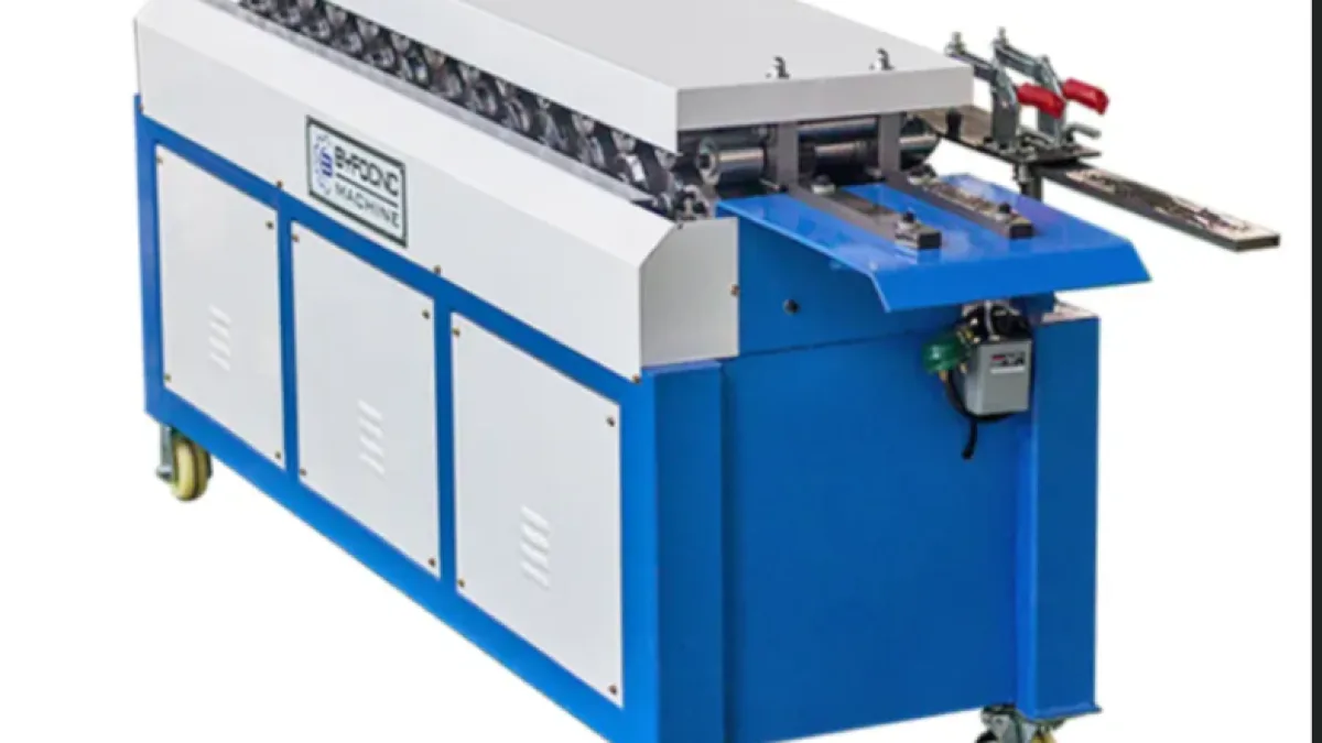
The T-15 TDF Flange Forming Machine is an industrial sheet-metal forming solution for producing integral flanges used in rectangular HVAC ductwork. It processes 0.6–1.5 mm sheet continuously, forming consistent connection profiles while reducing manual fabrication. The machine can also produce L-shaped clamps, helping duct manufacturers standardise components and increase workshop productivity.
T-15 TDF Flange Forming Machine Overview
The T-15 is intended for HVAC duct factories, sheet-metal workshops and ventilation-equipment manufacturers that need repeatable flange profiles. It uses a sequence of forming rollers to progressively shape the edge of a sheet-metal blank without cutting or separately attaching a conventional angle frame.
Its 4 kW motor powers the forming system, while the automatic material-feeding arrangement moves prepared sheet through the rollers. The resulting profile can be incorporated into rectangular duct sections and joined with a compatible flange assembly method.
The machine’s supplied working range covers sheet thicknesses from 0.6 to 1.5 mm. This range makes it suitable for several common light- and medium-gauge duct-fabrication requirements, subject to the sheet material, grade and project specification.
The T-15 configuration provides:
- Automatic sheet feeding
- Continuous roll forming
- TDF flange production
- L-shaped clamp production
- Heat-treated forming rollers
- Precision bearing support
- Heavy-duty industrial construction
- A specified flange height of 35 ± 5 mm
- A 4 kW drive motor
- Compatibility with 0.6–1.5 mm sheet
Final duct construction must still comply with the project’s approved drawings, pressure classification, sheet thickness, sealing requirements and applicable HVAC standards.
What Is a TDF Flange?
TDF commonly refers to a transverse duct flange formed directly into the edge of rectangular sheet-metal ductwork. Instead of manufacturing a separate angle frame and attaching it to the duct, the integral profile becomes part of the duct section.
During installation, two compatible flanged duct sections are brought together. Gasket or sealant is applied as specified, corners are installed, and clamps or cleats secure the connection around the perimeter.
A complete TDF connection normally involves more than the formed profile. Depending on the adopted system, it may require:
- Flanged duct edges
- Matching corner pieces
- Gasket or approved sealant
- Cleats or clamps
- Fasteners
- Reinforcement
- Approved joint spacing
- Suitable duct supports
The forming machine creates the flange profile, but it does not independently guarantee an airtight or structurally compliant duct joint. Profile dimensions, assembly materials and installation practices must work together.
How Does the T-15 TDF Flange Forming Machine Work?
The T-15 uses progressive roll forming. Rather than bending the complete flange in one movement, several roller stations gradually transform the sheet edge into the required shape.
A typical operating sequence follows these stages:
- Prepare the sheet. Cut the sheet-metal blank to the required dimensions and check its thickness, edge condition and squareness.
- Inspect the machine. Verify that guards, controls, rollers, electrical connections and emergency stops are in safe working condition.
- Set the material guide. Align the guide with the required sheet position so the workpiece enters the forming stations correctly.
- Start the forming system. Run the machine according to the approved start-up procedure.
- Feed the sheet edge. Introduce the prepared blank into the inlet and allow the feed system and rollers to carry it through.
- Form the profile progressively. Each roller station applies part of the required deformation until the final flange shape is produced.
- Support the emerging sheet. Larger panels should be supported so their mass does not twist the profile or pull the sheet out of alignment.
- Inspect the flange. Check height, shape, straightness and surface condition against the approved sample or drawing.
- Proceed to duct assembly. Form the other edges and complete the duct using the required corners, clamps and sealing method.
The sheet should never be pulled through the machine manually or forced into misaligned rollers. If the material jams or tracks incorrectly, the machine must be stopped and isolated before intervention.
Technical Specifications
The following specifications apply to the supplied T-15 configuration.
| Specification | Details |
|---|---|
| Model | T-15 |
| Machine type | TDF flange roll-forming machine |
| Primary application | HVAC rectangular duct-flange production |
| Motor power | 4 kW |
| Material thickness range | 0.6–1.5 mm |
| Specified flange height | 35 ± 5 mm |
| Material feeding | Automatic |
| Secondary component | L-shaped clamp |
| Machine weight | 1,400 kg |
| Machine dimensions | 2,700 × 730 × 1,100 mm |
| Roller construction | Heat-treated and quenched |
| Main operating method | Progressive roll forming |
| Supplied hand tools | One hexagon socket wrench and two standard wrenches |
The operating voltage, phase and frequency should be confirmed before installation. A 4 kW motor rating does not by itself establish the machine’s complete electrical connection requirements.
Buyers should also confirm whether the stated thickness range applies equally to galvanised steel, stainless steel and aluminium. Materials with different strength and spring-back characteristics may require separate settings, rollers or practical thickness limits.
Material Compatibility and Sheet Thickness
The T-15 is specified for sheet between 0.6 and 1.5 mm thick. The actual forming behaviour depends on more than nominal thickness.
Important material variables include:
- Metal type
- Grade
- Yield strength
- Tensile strength
- Coating type and thickness
- Surface hardness
- Sheet flatness
- Edge condition
- Rolling direction
- Protective film
- Material spring-back
Galvanised steel is widely used in HVAC duct fabrication because of its corrosion resistance and availability. Aluminium may be selected where lower mass or particular corrosion characteristics are required. Stainless steel can be used in specialised hygienic, corrosive or architectural applications.
However, stainless steel of a given thickness may require greater forming force than mild or galvanised steel. Aluminium can mark or distort if roller pressure and guidance are unsuitable. The buyer should therefore confirm the accepted material and grade, not only the thickness range.
Each incoming sheet batch should be checked for consistency. Variations in hardness, coating or actual thickness can alter flange dimensions and surface appearance.
Understanding the 35 ± 5 mm Flange Height
The stated flange height is 35 ± 5 mm. This indicates a nominal height of 35 mm with a published range from 30 to 40 mm.
Before production begins, the required finished profile should be compared with:
- Approved duct drawings
- Corner-piece dimensions
- Clamp or cleat geometry
- Assembly method
- Gasket position
- Duct pressure class
- Applicable construction standard
The tolerance shown in the general machine specification is broad for a mating component. Production quality control should establish a narrower internal target appropriate to the actual corner and clamp system.
A profile can appear properly formed while still creating assembly problems. Excessive height, insufficient return, distortion or inconsistent angles may prevent corners from seating correctly or create gaps at the joint.
A first-off sample should therefore be produced and assembled with the intended corner, gasket and clamp before beginning a long production run.
TDF Flange Production and L-Shaped Clamp Forming
A notable feature of the T-15 is its ability to support production of TDF profiles and L-shaped clamps. Producing compatible connection components within the same workshop can improve workflow and reduce interruptions caused by missing assembly hardware.
The L-shaped component should still be checked against the actual flange system. Important dimensions may include:
- Leg length
- Included angle
- Material thickness
- Straightness
- Cut length
- Edge condition
- Fit over the formed flange
The phrase “simultaneous production” should be understood in relation to the machine’s installed roller configuration. Buyers should verify whether flange and clamp profiles emerge from separate forming paths during the same operating cycle or require an adjustment.
Material-consumption calculations should include both the duct blank and clamp strip. Scrap from slitting or profile trials should also be included when estimating production requirements.
Production Capacity and Workflow Planning
The supplied information does not specify a forming speed. Buyers should request the rated speed in metres per minute and confirm the conditions under which it is achieved.
Practical output depends on:
- Forming speed
- Sheet length
- Number of edges formed
- Loading time
- Panel support
- Changeover time
- Inspection frequency
- Upstream cutting capacity
- Downstream duct assembly
- Operator experience
- Material consistency
A fast flange former will not maximise workshop output if sheet cutting, folding or corner assembly becomes the bottleneck. Capacity should be assessed across the entire duct-manufacturing process.
A practical workflow may include:
- Coil or sheet storage
- Cutting or blank preparation
- Notching
- Beading or reinforcement
- TDF flange forming
- Duct folding
- Seam closing
- Corner installation
- Sealing and clamping
- Inspection and identification
- Finished-section storage
The machine should be positioned to minimise panel turning, long-distance carrying and conflict with other fabrication activities.
Machine Footprint and Installation Requirements
The T-15 measures 2,700 mm long, 730 mm wide and 1,100 mm high. Its 1,400 kg mass requires a suitable floor and planned unloading procedure.
The machine footprint alone does not represent the complete operating area. Additional space is required for:
- Sheet infeed
- Formed-sheet discharge
- Operator position
- Electrical cabinet access
- Drive and roller maintenance
- Material staging
- Completed-panel storage
- Safe pedestrian movement
- Emergency access
Long sheets require clear space on both sides of the machine. Roller stands or support tables may be needed to prevent panels from sagging or twisting during forming.
Before delivery, confirm:
- Door and gateway dimensions
- Offloading-equipment capacity
- Machine lifting points
- Centre of gravity
- Floor load capacity
- Required anchors
- Machine levelling method
- Electrical cable route
- Main isolator position
- Lighting
- Ventilation
- Emergency-stop access
The machine should be installed level. An uneven base can affect roller alignment, bearing loading and sheet tracking.
Electrical and Power Requirements
The T-15 uses a 4 kW motor. The final electrical specification should identify:
- Rated voltage
- Number of phases
- Frequency
- Full-load current
- Starting method
- Control voltage
- Required protective device
- Cable size
- Earthing arrangement
- Main isolator
- Emergency-stop circuit
South African and other African facilities may use different supply arrangements. The machine’s nameplate and electrical documentation must match the actual site supply before connection.
Voltage instability can affect motor performance and control reliability. Where site power is unreliable, a qualified electrical professional should assess voltage regulation and protection requirements.
A generator should not be selected using the 4 kW motor rating alone. Starting current, power factor, other connected loads and generator performance must be considered.
Electrical installation and testing should be performed by appropriately qualified personnel under applicable local requirements.
Benefits of the T-15 TDF Flange Forming Machine
Consistent flange profiles
Progressive rollers can produce repeatable profiles when the machine is properly aligned and supplied with consistent sheet.
Reduced manual forming
Automatic feeding reduces the amount of manual manipulation required to form long flange profiles.
Increased workshop productivity
Continuous roll forming can process prepared sheet faster than multi-stage manual flange fabrication.
Integrated component production
The ability to produce L-shaped clamps supports a more coordinated duct-connection workflow.
Lower dependence on separate angle frames
An integral flange can reduce the need to fabricate and attach conventional external frames for compatible duct systems.
Durable forming components
Heat-treated and quenched rollers are intended to provide resistance to wear during repeated industrial operation.
Suitable thickness range
The 0.6–1.5 mm range supports several common rectangular duct-manufacturing requirements, subject to material strength and project design.
Compact machine width
A width of 730 mm can assist placement in workshops where lateral space is limited, although adequate infeed and discharge areas remain necessary.
Repeatable assembly
Consistent flanges can improve the fit of corners, clamps and gaskets, helping workers assemble standard duct sections efficiently.
Quality Control for Formed HVAC Flanges
Flange quality should be checked at machine setup, after material changes and throughout production.
Inspection criteria can include:
- Flange height
- Profile angle
- Return dimensions
- Straightness
- Corner compatibility
- Clamp fit
- Surface marking
- Coating damage
- Cracks
- Edge waves
- Panel distortion
The first-off inspection should use calibrated measuring tools and an approved profile sample or drawing. A short section can then be assembled with the actual corner and clamp.
If the profile drifts during production, possible causes include:
- Roller wear
- Loose guides
- Incorrect sheet position
- Material-thickness variation
- Different material hardness
- Bearing wear
- Roller contamination
- Machine misalignment
Operators should not compensate for a dimensional problem by forcing corners or over-tightening clamps. The forming issue should be identified and corrected.
Completed ductwork may also require leakage or pressure testing under the applicable project standard. The ANSI/SMACNA HVAC Duct Construction Standards provide recognised guidance on metal and flexible HVAC duct fabrication and installation, but the project engineer must determine the standard and edition that apply.
Safety When Operating a TDF Flange Former
A flange-forming machine contains rotating rollers and in-running nip points capable of drawing in fingers, clothing, gloves or tools. The sheet itself can also cause severe cuts.
The International Labour Organization’s machinery-safety code covers control systems, machinery guarding and protection from mechanical hazards. The machine should be assessed within the specific workshop environment before operation.
Key controls include:
- Fixed guards over transmissions and unused rollers
- Protected sheet entry points
- Accessible emergency-stop controls
- Lockable electrical isolation
- Controlled restart after power failure
- Clearly marked operator positions
- Adequate lighting
- Slip-free floors
- Safe sheet-support arrangements
- Trained and authorised operators
Operators should keep their hands away from the inlet and never attempt to guide material by reaching into the rollers. Push devices or designed feed supports should be used where required by the operating procedure.
Loose clothing, jewellery and unsecured hair can become entangled. Gloves may protect against sharp sheet edges during handling, but they can also increase entanglement risk near rotating machinery. The risk assessment should define where gloves may and may not be worn.
Roller adjustment, cleaning, jam clearing and maintenance should only begin after the machine has been isolated and all motion has stopped.
Maintenance and Roller Care
Regular maintenance supports consistent flange geometry and extends machine life.
A typical programme should cover:
- Roller cleaning
- Roller-surface inspection
- Bearing lubrication
- Gear and gearbox inspection
- Chain or transmission adjustment
- Guide alignment
- Fastener checks
- Motor inspection
- Electrical-terminal inspection
- Guard inspection
- Emergency-stop testing
- Foundation and levelling checks
Galvanising residue, oil, metal fragments and dirt can accumulate on forming surfaces. Contaminated rollers may mark the material or alter the profile.
Rollers should not be cleaned while rotating. Use only cleaning methods compatible with their finish and the processed material.
Bearing noise, increasing vibration, heat or inconsistent tracking should be investigated promptly. Continued production with a damaged bearing can affect multiple forming stations.
A recommended spare-parts kit may include bearings, seals, drive components, switches, contactors and specialised profile rollers. Buyers should obtain an illustrated parts list and lubrication schedule for the T-15 configuration.
Standard Accessories
The listed standard accessories are:
| Accessory | Quantity | Intended purpose |
|---|---|---|
| Hexagon socket wrench | 1 | Adjustment and removal of compatible socket-head fasteners |
| Standard wrench | 2 | Routine assembly and adjustment of compatible fasteners |
These hand tools support basic adjustments but do not represent a complete installation or maintenance kit. Site personnel may also require levelling tools, calibrated measuring instruments, approved electrical test equipment, lifting accessories and manufacturer-recommended lubricants.
Buyer Checklist for a TDF Flange Forming Machine
Use this checklist before placing an order:
- Confirm that the required profile is TDF-compatible.
- Provide a flange-profile drawing or approved sample.
- Confirm the nominal flange height.
- State the required profile tolerances.
- Identify the sheet-metal type and grade.
- Define minimum and maximum thickness.
- Confirm compatibility with galvanised coatings.
- Request performance confirmation for stainless steel or aluminium.
- Define the maximum sheet length and width.
- Confirm the forming speed.
- Clarify how the L-shaped clamps are produced.
- Check compatibility with corners and cleats.
- Confirm motor power.
- Specify site voltage, phase and frequency.
- Request the full electrical load and current.
- Obtain the electrical schematic.
- Confirm machine dimensions and net weight.
- Verify unloading and lifting arrangements.
- Determine floor and anchoring requirements.
- Plan sheet infeed and discharge space.
- Confirm guards and emergency-stop locations.
- Request operator and maintenance manuals.
- Define installation and commissioning responsibilities.
- Request operator training.
- Obtain a lubrication schedule.
- Identify recommended spare parts.
- Approve a formed-profile sample.
- Establish the acceptance-test procedure.
- Check applicable HVAC duct standards.
- Confirm every included accessory in writing.
How to Request the Machine Through Afrimart
Buyers can review the related Square HVAC Duct Making Machine and TDF Flange Forming Machine on Afrimart.
The live product page describes a broader TDF-forming equipment range, while the specifications supplied for this article identify a specific T-15 configuration. The final quotation should explicitly state:
- T-15 model
- 4 kW motor
- 0.6–1.5 mm material range
- 35 ± 5 mm flange height
- 1,400 kg machine weight
- 2,700 × 730 × 1,100 mm dimensions
- Required electrical configuration
- Installed roller profiles
- L-shaped clamp-forming arrangement
- Included tools and accessories
Buyers should attach a sample or drawing of the required profile and identify the sheet grade. This reduces the risk of receiving a machine with a visually similar but incompatible flange geometry.
Frequently Asked Questions
What does the T-15 TDF Flange Forming Machine produce?
It forms an integral TDF-style flange along sheet-metal edges used in rectangular HVAC ductwork. The stated configuration can also produce L-shaped clamps.
What sheet thickness can the T-15 process?
The supplied specification states a range of 0.6–1.5 mm. Compatibility should be reconfirmed for the exact metal grade because stainless steel, aluminium and galvanised steel have different forming characteristics.
What is the motor power?
The T-15 is equipped with a 4 kW motor. Voltage, phase, frequency and full-load current should be confirmed before electrical installation.
What is the specified flange height?
The stated flange height is 35 ± 5 mm. The actual production target should be aligned with the approved corner, clamp and duct-construction system.
Does the machine complete an entire duct section?
No. It forms the flange profile. Duct production may also require cutting, notching, beading, folding, seam closing, corner installation, sealing and inspection equipment.
Can the machine form stainless steel?
The supplied data provides a thickness range but does not define separate stainless-steel limits. Buyers should submit the exact grade and thickness for written compatibility confirmation and sample testing.
What space is needed for installation?
The machine measures 2,700 × 730 × 1,100 mm, but additional space is required for sheet feeding, discharge, operator access, maintenance and material storage.
Sources and Technical Review
This article was prepared from the supplied T-15 technical information, the related Afrimart TDF flange-forming machine page, the ANSI/SMACNA HVAC Duct Construction Standards reference, and the International Labour Organization’s machinery-safety guidance.
The supplied T-15 specifications differ from some values displayed on the broader Afrimart product page. The final model, profile, material range, electrical supply, dimensions and included equipment should therefore be confirmed in the approved quotation before purchase.